Category Archives: Uncategorized

Technology Developments of Gelcoats

Crystic® Gelcoats are durable and are formulated using the correct rheology for both brush and spray application.

R.Raghavan, Satyen Vora and Biju,K,
Satyen Scott Bader Private Limited

Introduction :
The durability of the composite moulding is highly dependent on the quality of its exposed surface. The Gelcoat is the face of the composite moulding as it provides both protection and surface aesthetics
Gelcoat can be applied by brush or spray, though developments in gelcoat technology and spray equipment have combined to markedly increase the use of spray application methods.

Crystic® Gelcoats :
Whichever application method is chosen, it is important to choose a good Gelcoat, specially formulated with correct rheology for both brush and spray application.

Crystic® Gelcoats are formulated to provide superior long term performance derived from 50 years of reliability, experience and innovation.

Latest technology gelcoats include very low colour change, market leading Crystic® Permabright, ultra low styrene emission Crystic® Ecogel and Crystic® Fireguard intumescent topcoats, designed to protect composites from fire.


 Crystic® Gelcoats are used for application such as marine, land transport and construction.

Weathering :
When gelcoated laminates are used indoors, durable and decorative mouldings are easily achieved.
For exterior applications, problems with discoloration, fading, loss of gloss may be encountered if the gelcoat is not specifically designed for the application.

12 months tests at Florida

Crystic® gelcoats and 18 base pigments have been thoroughly tested and qualified by subjecting them to 12 months in intense sunlight of Florida, QUV and Xenon weathering tests. In addition Crystic® gelcoats are subjected to 1 year osmosis and blistering tests before qualifying for application such as marine.

Blistering tests for marine gelcoats

Crystic® gelcoats and 18 base pigments have been thoroughly tested and qualified by subjecting them to 12 months in intense sunlight of Florida, QUV and Xenon weathering tests. In addition Crystic® gelcoats are subjected to 1 year osmosis and blistering tests before qualifying for application such as marine.

Monsoons and Gelling Problems – help yourself!

The monsoons will be here soon, and gelling problems and gel-time issues are not far away. A little knowledge can help you get to the root of the problem yourself. If you are aware of the curing mechanism and approach the gel-time problem equipped with the correct knowledge, you won’t have any of these seasonal problems at all.

OPEN MOLDING : Conventional Gel Coat—Troubleshooting

1. INTRODUCTION—Even under
the best of conditions, problems can occur due to accidents, mistakes and unanticipated changes. Listed are some of the various problems that can occur and how to solve them. Also remember that the gel coat is affected by the laminate, and good gel coat will not compensate for a poor laminate.

2. PROBLEM DIAGNOSIS—To isolate and diagnose the problem, give consideration to the following :

A. What does the defect look like?

B. Where does it occur? All over, random, isolated side or section?

C. Is it on all parts, some of the parts, or just one?

D. When did it first occur? Or when was it first observed?

E. Does it match up to a defect in the mold?

F. When were the defective parts sprayed?
1) Did it occur during a particular shift? Or from a particular spray operator?

2) Was it during a particular part of the day— when it was hot, cold, damp, or other?


G. Did the problem occur through all spray stations or just one in particular?

H. Where does it occur? In the gel coat film? Against
the mold? On the back side? Within the film?

I. What is the code, batch number, and date of the gel coat with which the problem is occurring? Were good parts sprayed from this batch or drum?

J. Was anything done differently, such as a change in catalyst level, spray operator, method of application, or weather conditions?

K. How would someone else identify or describe the defect?

L. What were the weather conditions at the time the part was sprayed?

M. What corrective steps were taken and were they effective?

N. Check the material or laminate that was applied to or on the gel coat.

Listed on the following pages are common gel coat problems and their usual solutions. Photographs illustrating many of these problems are also included.

Common Gel Coat Problems and Solutions

PROBLEM

                     CAUSE


SOLUTION OR ITEMS TO CHECK FOR
Air Bubble

Air pockets 
Check rollout procedures.

Alligatoring—a wrinkling of the gel coat, resembling alligator hide

Before laminating—


After or during lamination, or a second application of gel
coat ———————-

Raw catalyst ——–

Solvent ————–

‘Cured’ over-spray—-

Thin gel coat ——-

Insufficiently cured gel coat————-


Check for leaks or over-spray.

Do not reduce with solvents.

Check for contamination. Maintain a wet line.

Use a minimum of 12 mils, wet. Discontinuous gel coat film.

Catalyst level too high or too low. Temperature too low. Gel time too long. Time between coats or lamination insufficient. Moisture or contamination in the mold.

Bleeding—one color shows on another, typically when color striping——————–


Laminate Bleed (cosmetic problem only)———————-

Striping gel coat sagging over ‘cured’ gel coat —————-


Monomer in laminating resin ——

Gel coat back side cure —————–

Check sag resistance of ‘striping’ gel coat.
Spray stripe coat as soon as possible. Spray thin film of stripe color over the ‘wet’ base coat.Check for excessive monomer in laminating resin.Change gel coat.
Blisters —

Appear shortly after part is pulled, especially when put in sun——-


Appear after part in field ——————


Water blisters ——-

Unreacted catalyst or under-cure ——


Solvent, water, or oil

Air pockets ———

Unreacted
catalyst ————

Solvent, water, or oil ——————-

Various ————-

Check percent catalyst, catalyst over-spray, mixing, and leaks.

Check air lines, material, and rollers.

Check rollout.

Check catalyst levels and distribution, film thickness— 18 ± 2 mils.
Check air lines, materials, and rollers.
See Part Four, Chapter VII.5 on ‘Blisters and Boils’ tests.
Chalking (gel coats will oxidize/chalk over an extended period of time; degree of chalking is related directly to the environment

Dry, chalk-like appearance or deposit on surface of gel coat (premature) ———


Cure —————-


Contamination —-


Insufficient
buffing ————–


Poor mold
condition ———–


Under- or over-catalyzation, producing incomplete cure. Check air lines, material, and rollers. Check catalyst level, film thickness, water and solvent contamination.

Surface soil picked up from atmosphere.


Wipe buffed area with solvent rag. If gloss remains, area is okay. If gloss dulls down, part needs more buffing.


Reduce sanding and buffing requirement on parts by keeping molds in good condition.

Checking
(mud cracking)—
Single or groups of independent or cres- cent-shaped cracks —-
 

Poor integrity of the gel coat film —

Trapped vapor or incompatible liquid which blows through the gel coat film on aging. Check catalyst level. Check for water, solvent, etc. Chemical attack. Temperature extremes.

Craters—while spraying Chunks in the gel
coat —————–Equipment ———

Dirt in the gun or material. Material old and starting to gel; rotate stock. Strain (filter) the gel coat.

Clogged gun (clean). Improper atomizing air setting (too low).

Cracks —


Spider cracks radiating out from a central point or in circles (reverse impact) —————

Stress cracks (cracking in parallel lines) ———


Impact from laminate side ——


Excessive gel coat film thickness —–


Mold mark ———

Impact ————–


Stress due to
flexing ————–


Mold mark ———


Check on handling and demolding procedures. Caution people about hammering on parts.

Use a mil gauge and do not go over 24 mils.


Defect in the mold.

Be careful.


Excessive gel coat thickness. Laminate too thin.
Pulled too green; laminate under-cured. Demolding or handling procedure. Sticking in the mold.


Defect in the mold.

Delamination—

In spots ————–


Large area ———–


Contamination


Gel coat too fully cured


Contamination —-


Unbalanced
laminate ————


Check for dust, solvents, moisture, catalyst getting onto the gel coat surface. Excess mold release wax floating through to the gel coat surface, creating areas that will not adhere.

Check for high catalyst level. Letting the gel coat cure too long, such as overnight; skin coat, rather than leave on the mold for long periods of time. Excess mold release wax or wax in the gel coat.

Solvent wiping, then waxing (around taped off areas),

Dry fiberglass.

Dimples—in the gel coat surface

Contamination


Other

Check for water, solvent, or improperly mix catalyst. Over-spray. Seedy resin. Excess binder on the glass mat.


Thin laminate or gel coat. Very dry laminate. Pin air entrapped. Post-curing of the laminate.

Dull gloss—on the gel coat—

When part is pulled –


When and after part is pulled ————–


Rough mold ——–


Mold buildup ——


Polystyrene buildup —


Dirt or dust on mold —


Solvent or water —


Raw catalyst ——-


Rough PVA or wet PVA —————–


Insufficiently cured gel coat or laminate —


Polish out mold.


Wax and buff with cleaner. In most instances, what is called wax buildup is actually polystyrene buildup and should be treated as such.


Sand or scrub with brush and strong solvent; read precaution on solvent before using. DO NOT USE STYRENE.


Clean the mold. It is best to clean in the spray booth just prior to gel coating. Time span should be as short as possible between cleaning and gel coating. Use a tack rag.

Check for solvent or water. Drain water traps regularly.

Start catalyst flow from gun away from the mold. Only catalyzed gel coat should be sprayed into the mold.


Check spray technique.


Correct excessive or insufficient catalyst level in gel coat and laminate. Wait longer before pulling.


Check for low temperature (minimum of 60ºF). Check for contamination: water, air or solvent.

Dull or soft spots—at random ————— Gel coat uneven —


Catalyst poorly mixed into either gel coat and/or laminate ——


Trapped solvent in gel coat and/or laminate ————


Trapped water in gel coat and/or laminate.
Insufficient

catalyst —

Poor breakup; use three passes.


Mix catalyst thoroughly or make equipment
adjustments for good catalyst mix. Equipment surging (material pump and/or atomizing air). Improper cata lyst settings (high or low). Gun held too close to mold.


Check cleaning procedure. Check catalyst level with equipment using solvent reduced catalyst.


Drain lines and correct the problem. Confirm correct catalyst concentration.

Fading—see also water spotting ——- Poorly cured gel coat —————–


Improper cleaners or chemicals——–

Check catalyst levels and film thickness (18 ± 2 mils).


Do not use strong alkaline or acidic cleaners.

Fiber pattern and distortion—in parts


Insufficient cure —


Transferred from
mold —————-


Glass cloth ———


Woven roving ——


Gel coat too thin —

High exotherm of laminate ————


Correct excessive or insufficient catalyst level in gel coat and/or laminate. Wait longer before pulling, Do not pull while laminate still has heat. Check for low temperature. Check for contamination by water, oil, or solvent.


Refinish mold.


Too close to the gel coat. Should have two layers of cured 1.5 oz. mat or equivalent chop between gel coat and cloth.


Too close to the gel coat. Should have three layers of cured 1.5 oz. mat or equivalent chop between gel coat and woven roving.

Use 18 ± 2 mils, wet.


Cure laminate more slowly. Laminate in stages. Use lower exotherm laminating resin.

Fisheyes

Water, oil, or silicone contamination —–


Dust / dirt on mold —


Gel coat film too thin –


Low viscosity
material ———–

Drain air lines. Check mold release wax. Excess and/or fresh coat of wax is worse.


Check lubricating materials used within the equip- ment. Use tack rag.


Use 18 ± 2 mils in three passes.


Old material—rotate stock.

Waste Management in FRP

Waste Management in FRP has been very tricky issue so far. Many attempts are seen in the markets to convert waste in useable form.  However, economic viability generally remains the main hurdle here.

This is an outline of one such attempt to use existing waste. Here the thermosetting, the UV resistance and the maintenance-free properties of FRP have been utilized. Long strips of FRP moldings are generated with a width of ½” to 2”. These strips are used just like strips made from bamboo. The damaged polye

ster films are also used to make the walls water tight. It is a normal practice to replace old bamboo strips every year as they are degraded due to rainy season and heat (various climatic conditions during t
he year). FRP strips are in use for almost six months including rainy season and the results are satisfactory


The benefits to the user (farmer)

The farmer is very happy as he saves on material costs and more importantly , on labor costs involved in the removal and reinstallation of new strips. Besides, the look is also better. One farmer who used these strips said, “I am now comfortable for the next 10 to 15 years. I am only worried that inside supporting wooden frame might be decayed or damaged due to white ants or so”.

The FRP manufacturer has now been encouraging people to collect the FRP strips from their factory and use it to cover shades and animal Gotha’s.  Material is available at zero cost.

Many farmers are showing interest in this particularly due to maintenance free material. The photos accompanying this write-up give you a clearer picture of how this is done. The manufacture also gave these strips to a UPS manufacturer at no cost. The UPS manufacturer fits these strips on the M.S. racks. Batteries are stored on these racks.  FRP gives corrosion resistance.

LANTOR COREMAT®

The flexible core and liner for hand lay-up and spray-up processes

For decades, Lantor Coremat® has been considered the world standard for flexible bulker mats and print blockers used in hand lay-up and spray-up processes. All Coremat® grades consist of a polyester non woven containing microspheres. They offer a cost effective increase in stiffness and weight-savings in materials and an excellent surface finish.

Lantor Coremat® Xi
• The cost effective solution for open mould processes
• Is used as core material and/or print blocker
• Is a polyester nonwoven and compatible with all regular types of resins, including Polyester, Vinylester, Phenolic and Epoxy
• Is suitable for hand lay-up and spray-up processes

Applications Lantor Coremat® Xi
Marine : hulls, decks and structures of boats and yachts
Transportation : parts and panels of cars, trailers and trucks
Mass transit : interior and exterior of trains, light rail and buses
Leisure : kayaks, surfboards, pools and tubs
Industrial : cladding panels, containers and tanks

Notification
Keep Coremat® Xi away from direct sunlight, therefore store Coremat® Xi in the original bag. This will ensure proper functioning of the resin indicator. Please note that the resin indicator is not a guarantee that sufficient resin has been applied, but strictly a control mechanism to identify dry spots. Always check resin content

Dimensional data

Properties Xi 1 Xi 2 Xi3 Xi 4 Xi 5
Thickness mm 1,4 2,0 3,0 4,0 5,0
Roll length m 130 80 50 40 30
Roll width m 1 1 1 1 1
Resin uptake kg/m2 0,8 1,2 1,8 2,4 3,0
Dry weight g / m2 45 55 80 105 125
Density impregnated kg/m3 630 630 630 630 630

Typical mechanical properties of Lantor Coremat
Xi* impregnated with unsaturated polyesther resin

Mechanical properties Unit Value Test method
Flexural strength MPa 11 ASTM D790
Flexural modulus MPa 1100 ASTM D790
Tensile strength across layers MPa 4 ASTMC297
Compression
strength: 10% strain
MPa 10 ISO 844
Shear strength MPa 5 ASTM C273-61
Shear modulus MPa 35 ASTM C273-61
*Lantor Coremat ® Xi 3

Marine
Lantor and Marine     

   A major market for Lantor composites is the Marine industry. The marine segment has adopted composite materials for over 4 decennia now and has been increasing the use of it ever since. Design flexibility, lightweight and excellent surface finish are important topics in this composite market segment.

With its flexible Coremat® grades Lantor enables the possibility of design flexibility and lightweight laminate manufacture in the marine industry. Increasing the surface quality of boats can be done by their special surface enhancement grades and the Finishmat® products.

Lantor Composite materials are used in a wide range of pleasure boats from small sailing boats to huge motor yachts. This is because Lantor materials are suitable for a wide range of manufacturing processes within the marine industry.

Wind Energy

Lantor and Wind Energy
One of the fastest growing markets for Lantor Composites is the Wind energy market. Except for the tower, all the visible parts of a wind turbine are made of FRP where the blades are the major components. With increasing demand of wind turbines the cycle time of producing wind turbine parts need to go down. To be able to compete with other energy sources total cost of energy of wind also needs to decrease.


Lantor flexible core grades can be of great help with these challenging topics when looking at the composite parts of a wind turbine.

For the nacelle housing and spinners, Coremat® and Soric® grades can help to build up laminate thickness fast and therefore help to reduce cycle times. In both the open mold and closed mold processes used to make these parts, Lantor products help to reduce glass and resin use and can therefore reduce cost significantly.

In wind turbine rotor blades a good flow regulation of resin during the production process is needed for high quality products. A special Soric® grade that is easy handled in the process and has very secure and stable flow properties helps to increase quality of the overall product.
Because of years of expertise in the wind energy market, Lantor can assist in laminate build-up solutions and do calculations for an optimal use of the different composite materials and to optimize the production cycle times of the specific products.

The Flammability of Polymers

excerpt from the Handbook of Plastics Testing Technology (Society of Plastics Engineers Monographs) by Vishu Shah

Plastic materials have been under considerable pressure to perform satisfactorily in situations involving FIRE, because of their increased use in homes, buildings, appliances, automobiles, aircraft and many other sectors of our lives. Before getting into discussion on FR tests and testing procedures, it is necessary to understand polymers as they relate to flammability. Polymer’s inherent flammability can be divided into three basic classes: Inherently Flame Retardant, Less Flame Retardant, and Quite Flammable.

When a polymeric material is subjected to combustion, it undergoes decomposition which produces fragments at the polymer surface. The fuel produced in this process diffuses to the flame front, where it is oxidized, producing more heat. This, in turn, causes more material decomposition. A cyclic process is established, solid material is decomposed, producing fuel which burns, giving off more heat, which results in more material decomposition. To reduce the flammability of a material, this cycle must be attacked in either the vapor phase or at the solid material surface. In the vapor phase, the cycle can be inhibited by adding certain additives to the polymer that disrupt the flame chemistry when vaporized. Bromocompounds and chlorocompounds with antimony oxide operate in this manner. Solid phase inhibition may be achieved by including additives in the polymer that promote the retention of fuel as carbonaceous char as well as providing a protective insulating layer. This layer prevents further fuel evolution. Few other solid phase approaches involve the use of heat sinks, such as hydrated alumina, which absorb heat and release water of hydration when heated, or alter the decomposition chemistry to consume additional heat in the decomposition process.
No discussion on polymer’s flammability can be considered complete without discussing the formation of smoke and the generation of toxic gases. Smoke impairs the ability of occupants to escape from a burning structure as well as the ability of fire fighters to carry out rescue operations. Many tests have been developed to measure smoke density and toxicity. The material’s ability to burn depends upon fire conditions as well as polymer composition. Actual fire conditions are difficult to simulate and therefore we are forced to rely upon small and large-scale laboratory tests to predict combustibility, smoke density and toxicity. The flammability of materials is influenced by several factors :

• Ease of ignition – How rapidly a material ignites.
• Flame spread – How rapidly fire spreads across a polymer surface.
• Fire endurance – How rapidly fire penetrates a wall or barrier.
• Rate of heat release – How much heat is released and how quickly.
• Ease of extinction – How rapidly the flame chemistry leads to extinction.

Smoke of evolution

Toxic gas generation.

Flammability Tests

Organization

Name of test

Procedure Id number

Specimen size (in.)

Number of specimens

Angle of specimen

Ignition source

Properties measured

ASTM

Rate of burning : flexible plastics 0.050 in. and under

D-568

1 X 18

3

Vertical

Bunsen burner

Burning rate, average time and extent of burning

ASTM

Rate of burning : Rigid plastics over 0.050 in.

D-635

1/2 X 5 X thickness

10

Horizontal

Bunsen burner

Burning rate, average time and extent of burning

ASTM

Incandescence resistance of rigid plastics

D- 757

1/2(W) X 4.57(L) X 1/4(T)

3

90d to source

Silicon carbide incandescence rod

Burning rate, average time and extent of burning


Organization

Name of test

Procedure
Id number

Specimen size (in.)

Number
of specimen
s

Angle of specimen

Ignition source

Properties measured

ASTM

Ignition
properties of plastics :
Procedure B

D-1929

3 g wt. sheet size 3/4 X
3/4 X 5

Horizontal

Hot air ignition furnace

Flash and self-ignition temperatures

ASTM

Oxygen Index flammability test

D-2863

1/4 X 1/8 X
5

10

Propane
flame in oxygen and
nitrogen
atmosphere

Oxygen
Index

ASTM

Surface
burning characteristics of building material

E-84

20 X 300

1

Horizontal

Gas/air mixture

Flame spread
index smoke
density

ASTM

Flame height,
time of burning, loss
of weight :
Cellular plastics, Vertical position

D-3014

10 X 3/4 X
3/4

6

Vertical

Gas burner

Loss of weight and time of extinguish- ment

ASTM

Rate, extent,
and time of burning of flexible thin plastic sheeting

D-1433

3 X 9

10

45d

Butane burner

Burning rate, extent and time of burning, visual characteristics

Federal Test Method Standard

Flame resistance of difficult to ignite plastics

FTMS 406
Method
2023

5 X 1/2 X
1/2

5

Vertical

Electric coil and spark plugs

Ignition
time, burning time, flame travel

UL

Flammability
of plastic materials

UL 94V-0

1/2 X 5 X
thickness

5

Vertical

Bunsen burner

Rate of burning

UL

Flammability
of plastic materials

UL 94 HB

1/2 X 5 X
thickness

3

Horizontal

Bunsen burner

Rate of burning

UL94 Flammability Tests
UL 94, developed by Underwriters Laboratories, is one of the most widely used and most frequently cited sets of flammability tests for plastic materials. The UL flammability tests include a standard burning test applied to vertical and horizontal test bars, from which a general flammability rating is derived. There are four basic tests for classifying materials in different categories as mentioned below:
1. Horizontal burning test for classifying materials (94 HB).
2. Vertical burning test for classifying materials (94V-0, 94V-1).
3. Vertical burning test for classifying materials (94-5V).
4. Vertical burning test for classifying materials (94 VTM-0, 94 VTM-1, or 94 VTM-2).


Steps in meeting Flammability Requirements
1. The first step in meeting flammability requirements is to carefully define the application in details. This will help narrow the list agencies you may have to deal with.
2. Determine the appropriate agency that deals with your application. For example, if the application has something to do with building industry, you may want to contact one of the consulting agencies for building and construction organizations. If the application is a plastic cabinet that houses electrical components, UL is the organization to contact.
3. Once the application is defined and the governing agency is narrowed down, you may proceed with the designing and material selection. An important thing to remember at this stage is to specify the material to your design and not vice versa. The material selection process can be expedited by consulting published sources, such as UL-recognized component directory that lists plastics according to performance as tested by UL 94. Modern Plastics Encyclopedia’s flammability chart is another source of information for preliminary screening of the materials.
4. Once the preliminary decisions have been made on the type of material that will meet the requirement of the application, the material supplier or a custom compounder can be consulted for specific grade of material.
5. If the code or standard required, an independent laboratory should be consulted.


About the Author
VISHU SHAH is President and cofounder of Performance Engineered Products, Inc., a custom injection molder located at Pomona, California.

Book Details
Handbook of Plastics Testing Technology, Vishu Shah, Wiley, New York 1984,
pol.1985.130230111. ISBN, 0471078719


Release Agent Information Of Paste Wiz to avoid regular use of PVA + WAX.


The current problems molders face while us of PVA + WAX.
Many of you are molders who use the hand lay-up process & simply use a PVA + WAX release agent for release. When you use PVA, you need to wait until the wax application that precedes it, is buffed & dry. However, in busy times, as well as in the monsoons, most molders find it difficult to achieve the number of planned releases. Additionally, molders are always concerned that it makes their molds dull, and also that the regular use of PVA and WAX results in mold surface fungus.

Many times, when one expects 200- 300 releases out of the mold, you only end up with 100 – 120 releases. In an increasingly competitive market, with customers demanding better rates, you are compelled to keep costs down.

PASTEWIZ from Axel Plastics – An affordable solution for molders

A new wax named PASTEWIZ from Axel Plastics USA, might just solve all these problems. PASTEWIZ is a paste mold release agent for wood, plaster, fiberglass and metal molds. It effectively seals porous areas of mould surface resulting in a smoother mold surface. It is also specially designed for Hand layup, Spray up & LRTM application.

Additional Benefits of PASTEWIZ

• Good, long lasting gloss to the mold that translates to a well finished job.
• No use of PVA – So no washing/cleaning before painting or secondary bonding
• Since there’s no PVA, there is consequently no problem of fungus on the mold
• Better productivity.
• Saves time, so it works well even during heavy production and in the rainy season.
• It is cost-effective when you compare regular application of PVA and WAX with the number of releases ones gets out of PASTEWIZ

More Information

PASTEWIZ has been developed for ambient and high temperature applications. A customer can expect at least 10 to 15 releases on a plain surface mould and 7 to 8 releases on a curve part mold. Please contact us to know more about PASTEWIZ.

A Single Product for your sealing and bonding requirements – PliogripTM 3010 MSP MS Polymer Sealant

PLIOGRIP® MS POLYMER Sealants are based on single component modified silane technology. MS polymers are used for sealing and bonding interior as well as exterior parts in the automotive, building and industrial sector.

Key Features :
High performance moisture curing sealant with high elasticity between – 400C to +1150C
Excellent adhesion on painted and non painted surfaces e.g. rubber, glass, wood, metal and concrete.
Solvent free and exhibits excellent resistant against aging and chemicals
UV Resistant
No hazardous chemicals
Suitable for bonding wide spectrum of Materials
> Metals, Sheet Steel (Galvanised, Plated & Painted)
> Untreated or Anodised Aluminium
> Brass
> Copper
> Glass
> FRP/GRP (Fibre glass reinforced plastic)
> Thermoplastics


Applications :

Building & Construction :
Glazing
High quality glazing sealant, especially suitable for
burglar safe glazing systems
Joint Sealing Applications
Sanitary Installations
Pharmaceutical Doors

Automotive & Commercial Vehicles :
For coach-work and metal surfaces,
for bonding metal to metal (can absorb vibrations).
Panel Bonding
Seam Sealing
Roof Bonding
Glass Bonding

Industrial & Assembly Applications :
Bonding and sealing applications of different substrates in various industrial applications.
Stiffener bonding.
Versatility in workability due to paintable and wet surface bonding   characteristics.
Floor bonding in Marine Industry (Floating Jetty)
Chequered Plate Bonding
Acoustic enclosures
Cable Trays


                        ]


Silicone Mold Making Materials

Molds are made using silicon rubbers, and used for a variety of purposes

Silicone mold making products are designed to replicate original parts, old or new to exact dimensions. There is an infinite variety of applications for these materials. From art work and picture frames to figurines to prototypes to candy, it is all possible!

Application Examples

Industrial Mass Production

For small production runs in a variety of different designs: MOLDSIL flexible molds have proven to minimize unit mold costs.
In particular this applies to models or industrial mass production of :
• Plaster working molds and models for porcelain and sanitary ceramics manufacture
• Ornamental door panels and window frames , mirrors and picture frames
• Reproduction furniture
• Hand-painted figurines and sculptures from filled casting resin
• Shaped foodstuffs (chocolates, portions of butter, decorations for ice cream)
• GRP laminates (boats, surfboards, tanks, etc)
• Electroforming of dashboards, automotive interior trim, etc.

Rapid Prototyping
In the light of increasingly demanding requirements of the industry, processes such as rapid prototyping must be able to reproduce an original model with honest reproduction in large quantities. This is usually done by vacuum casting in silicone elastomer molds.

The technique is used to produce prototypes for
• Display models
• Design models
• Functional models
• Pre-series models
• Wax Models
• Small series
For any model and any reproduction material, the PLATINSIL range of silicone rubbers offers an ideal grade for vacuum casting (soft tooling).

Restoration
Easy to process and requiring no expensive equipment, MOLDSIL and PLATINSIL grade rubbers are ideal for hobbyists, but are also valued
by restorers, conservationists, archeologists and museum technicians for in-situ reproduction of originals.

A main application is the production of complex and creative parts, such as :
• Replicas of irreplaceable originals for display purposes
• Decorative prefabricated concrete parts
• Garden furniture
• Designer Candles
• Wax positives for investment casting of high-melting metals by the lost wax technique
• Ornamental frames, buttons ….
• Artificial Jewellery
• Electroformed articles

Which product to choose? Questions to consider
• What material will be cast into the mold?
• What are the temperature requirements?
• How hard or soft must the mold be?
• What are the cure time requirements?
• How complex in shape is the original?
• Are there many undercuts in the original?
• Is color a consideration? Transparency required?
• Is there a reason a container cannot be built around the original to
to contain the silicone rubber?
• What is the original made of?
• Does the original contain sulfur amines, butyl, tin soap catalysts, etc.?
• How much shrinkage can be tolerated?
• What are the viscosity requirements of the uncured silicone rubber?

Silicone Drivers :

Cost Competitiveness          Metal tooling may cost more
Fast Metal                            tooling can take weeks to make
Accurate Snap                     fits can even be made
User Friendly                       Easy to process
Simpler Molds                      Fewer parting lines means less finishing work
Good Mold Life                    15 to 25 duplicates may be needed


Silicone mold making materials :
Silicone Features and Benefits
Attributes : Detailed reproduction, long mold life, easy de-mold

Features Benefits
• Low surface energy wets part for superior detail reproduction
• Flexible and ease of release
• Superior chemical and high heat Resistance
• Low shrinkage
• High elasticity
• Faithful reproduction of even the most complex originals
• Easy de-molding of undercuts
• Provides long mold life (multiple parts) even with aggressive resins
which develop high exothermic temperature during cure
• Excellent dimensional stability
• Readily stretched for easy part removal


Silicone Material Properties :
Attributes : Detailed reproduction, long mold life, easy de-mold

Features Benefits
• High Tear Strength
• Fast Curing
• Flexible Cure Cycle
• Food contact Possibilities
• Low shrinkage
• Molds resist tearing when stretched for part removal
• Silicone molds can often be built quicker than competitive materials (Ex: latex metal …)
• Adapts to a wide range of requirements
• Excellent dimensional stability
• Platinum cure systems meet food contact requirements


Material choices for different applications: Comparison

Condensation Cure RTV Addition Cure RTV
• MOLDSIL (Tin Catalyst)
• Low durometer (5-40)
• Soft, flexible, captures detail
• Room temperature cure only
• Low viscosity for easy pour
• Low shrinkage (0.1%-0.3%)
• Resistance to sulfur-based clays
• Moisture-dependent cure
• Alcohol, water by-product
• PLATINSIL (Platinum Catalyst)
• High durometer (25-70)
• Dimensional stability
• Room temperature or heat accelerated
• High viscosity
• Extremely low shrinkage (<0.1%)
• Recommended patch test for cure inhibition; excellent for epoxies and urethanes
• Self-contained cure
• No by product

For full-fledged comparison charts detailing the technical comparison of mold making rubber grades and silicon rubber grades, write to us on response@elink.co.in

Types of Molds

• BLOCK MOLD: Where the rubber mold completely fills the area between the master and mold support. The exterior of the mold does not conform to the shape of the master.

• SKIN MOLD: A thin mold which closely follows the contours of the master. This type of mold is typically applied with a brush and is prepared in multiple layers. This process uses less material and is more flexible than a block mold.

• GLOVE MOLD: A hybrid of a skin and block mold. Usually measures 3/8″ in thickness and requires a mother mold. It can be poured in one application.

• MOTHER MOLD: A structure built around the silicone mold in order to maintain proper dimensions of produced parts during the casting process.

Mold making – typical process steps
• The Master Part
• Building the Mold
• Prepare the Silicone
• Pour/Cure Silicone
• De-mold
• Duplicate Part

Most mold making material manufacturers are also willing to custom design a product based on customer requirements. Contact us for more information response@elink.co.in

Carbon Fibers – the untapped potential!

An informative article detailing everything you would want to know about Carbon fibers, including the global scenario and the Indian context!

Historical Perspective
The commercial production of carbon fiber can be traced to 1969, when Courtalds in the UK opened a 5 Tonnes a year plant to make staple fiber that had a Tensile Strength of 1900 Mpa and Modulus of 180Gpa. From the days of its origin the name carbon fibers has come to be synonymous with Aerospace and Aero Structures which still continue to be the most profitable sectors for Carbon fiber manufacturers worldwide.

Though the worldwide market size for carbon fiber products is difficult to estimate, research has indicated this to be between 34,000 – 35,000 MT as of 2009. Aerospace still remains a major contributor, accounting for 30% of the total sales volume and 50% of the total sales value. Not surprisingly, the pricing of carbon fibers and its availability over the years has been closely tied to the demands of the Aerospace Industry. This correlation has meant that carbon fiber suppliers have been very erratic with their pricing and supplies. Their inability to supply fibers to Industrial applications during periods of high demand from Boeing and Airbus has resulted in the Industry growing at a sluggish pace.

The barriers to entry into the Aerospace and Defense sectors still remain very high – Characterized by high capital investment, long qualification cycles and technology intensive processes make it a challenge to serve this industry. This dichotomy of needs between the producer and end users needs to end if we are to see mass scale commercialization of carbon fiber composites. It is also interesting to note that while the Aerospace sector contributes 30% of total sales, the Industrial composites segment, i.e. Wind, Infrastructure, CNG, Auto, etc contribute the remaining 70% and have been experiencing double digit growth.

The applications for carbon fibers on the Industrial side and the wide variety of products and composite manufacturing processes that are available provide an attractive option to composite fabricators in emerging markets to develop new and innovative products.

Zoltek was one of the first companies to understand these dynamics and break away from it to ensure market-driven fair pricing and sufficient availability to support Industrial applications. Today Heavy Tow, Standard modulus or commercial grade carbon fibers with their lower costs structures and excellent performance are opening new doors for composite manufacturing. For the purpose of this article the focus will be on Industrial applications and commercial grade carbon fibers.

Manufacturing Method
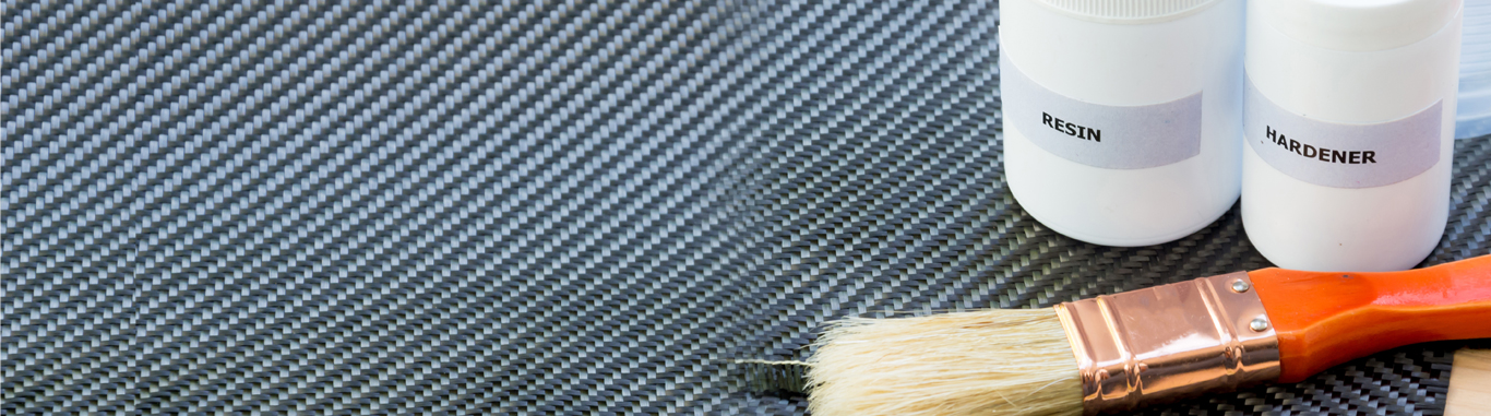
The raw material used to make carbon fiber is called the precursor. About 90% of the carbon fibers produced are made from Polyacrylonitrile (PAN). The remaining10% are made from rayon or petroleum pitch. All of these materials are organic polymers, characterized by long strings of molecules bound together by carbon atoms. The exact composition of each precursor varies from one company to another and is generally considered a trade secret. During the manufacturing process, a variety of gases and liquids are used. Some of these materials are designed to react with the fiber to achieve a specific effect. Other materials are designed not to react or to prevent certain reactions with the fiber. As with the precursors, the exact compositions of many of these process materials are considered trade secrets.

The process for making carbon fibers is part chemical and part mechanical. The precursor is drawn into long strands or fibers and then heated to a very high temperature with-out allowing it to come in contact with oxygen. Without oxygen the fiber cannot burn. Instead, the high temperature causes the atoms in the fiber to vibrate violently until most of the non-carbon atoms are expelled. This process is called carbonization and leaves a fiber composed of long, tightly inter-locked chains of carbon atoms with only a few non-carbon atoms remaining. The repeated heat treatments in a carbonization oven and the application of sizing and finishing complete the manufacturing process.

Global Scenario
Carbon fiber today has come to be accepted as an established material for sectors that demand high performance. With the ability to offer weight reduction, excellent strength & Stiffness, corrosion resistance and excellent fatigue properties, carbon fibers are increasingly becoming the material of choice for FRP’s. Although it cannot compete in terms of price with GRP (Glass reinforced plastics), it offers performance benefits that cannot be met with GRP. Well designed and thought out CFRP (Carbon fiber reinforced plastics) parts are today able to achieve cost structures similar to traditional GRP parts.
The current worldwide production of PAN based carbon fibers is estimated at 70,00MT out of which commercial grade carbon fibers constitute about 20,000MT. Toray is currently the market leader with around 35% of the installed capacity, closely followed by Zoltek with about 30% and Toho – Tenax. Other significant players include SGL, Hexcel, Cytec, Mitsubishi, etc. AKSA & Formosa are other new entrants into this market. Carbon fibers are broadly classified into 3 sections based n their modulus. Standard Modulus – Modulus <250 GPa, Intermediate Modulus – Modulus <350Gpa, High Modulus – Modulus >300. Further, small Tow or Aerospace carbon fibers are defined as having a filament count of less than 24,000 and Commercial grade carbon fibers are defined as fibers having a filament count of more than 24,000 filaments in a tow bundle. The difference between the two is essentially in the purity of the precursor and to an extent the processing technologies. Aerospace grade fibers offer better properties and are easier to use but much more expensive than commercial varieties. The economies of scale related to producing commercial grade carbon fibers make them cheaper and more attractive. Commercial grade carbon fiber from Zoltek is today available at $10/lb versus Aerospace grade carbon fibers from Toray, Hexcel and Toho – Tenax sometimes being 3 -4 time more expensive.

Europe and North America still account for about 50% of all the total carbon fiber consumption. Asia accounts for about 20% of the total consumption with China leading the pack by some distance. In terms of Industry, Aerospace accounts for about 25% of current carbon fiber consumption followed by wind energy at about 10%, Automotive 5% with Civil engineering, Sporting goods, Marine and other industrial application completing the pie. The share of Industrial applications – Wind Energy, Infrastructure and Pressure vessels is expected to grow at the rate of about 35% every year over the next 5 years.


Product Forms, Process options and Typical End Products

Continuous Tow
3K,12K,24K,50K
Filament Winding Pultrusion
CNG Tanks, Pultruded Rod, Sporting goods etc.
Prepreg Tapes
Different Resin Systems
Autoclave, Vacuum Bagging
Wind Energy, Aerospace, Sporting goods
Chopped Fibers
Different Lengths
Injection molding, SMC, BMC, LFT. Compression Molding
Automotive, Electrical components. Static Dissipation
Milled Fibers
Injection molding, Dispersion
Buoyancy modules, Static Dissipation etc
Uni Directional & Multi Directional Fabric
100 – 900GSM
Infusion, VARTM, RTM
Wind Energy, Automotive, Structural applications
Woven Fabrics
Different weave patterns
Infusion, VARTM
Automotive, Secondary reinforcement. Industrial.


A wide variety of Intermediate carbon fiber product forms are today available for processing into composites. The usage of Prepregs and Uni Directional fabrics remains to be very high. Chopped carbon fibers are increasingly finding their way to Thermoplastic and Thermoset application for Automotive structural or inner body components. The usage of carbon fiber tow for filament winding applications is well documented and used to manufacture a variety of products from rocket motor casings to CNG pressure vessels. Hybird product forms like +/-45, 0/90 Non Crimped Mutidirectional fabric, tri axial fabrics, SCRIM’s, Carbon non woven felts, Tri axials fabrics and Carbon – Glass Hybrid fabrics are also available for specialty applications. The gamut of available products today allows composite manufacturers to pick from a wind range of intermediate product forms as suitable to their application.

The Indian Context
The domestic market for carbon fibers has remained virtually stagnant due to poor availability, high prevailing prices and lack of support from carbon fiber manufacturers. The consumption of carbon fibers in India is estimated at around 50MT and this has largely been driven by the Defense and Aerospace sector. The lack of guidance in terms of choosing the right material, right processing technology and limited carbon composite design expertise has resulted in decimal level growth in the Indian market. In terms of carbon fiber usage India remains an aberration to the world standard. However, it is safe to believe this trend is set to change – A large part of this change will be driven by the needs of the Wind energy industry and the CNG pressure vessel market. The infrastructure and Automotive sectors are also beginning to move towards understanding and utilizing large volumes of carbon fiber composites. That said, apart from a few large technically capable organizations in India most fabricators remain low tech, relying on Hand lay up and infusion as primary molding technologies. For these SME’s to become a part of the mainstream there has to be a rapid movement towards advanced processing technologies like VARTM, prepreg and filament winding. Companies worldwide engaged in the use and manufacture of composite are today looking at India as a manufacturing base and to be a part of this global growth organizations must push towards developing better processing capability, design capability and testing facilities. The cost barrier can only be breached when companies are willing to invest in R&D. With companies such as Zoltek, Toho, Toray looking at India as a potential market the fiber availability situation is hopefully set to improve. The presence of large multinationals such as Bombardier, Boeing, Caparo Composites, Vestas, etc will only enhance the knowledge base and provide a technically competent workforce that this industry desperately needs.


                                                                               Manufacturing process in 2010 –                                                                          Composites applications in 2010 –
random data                                                                                                                      random data


Platinsil’s High Performance Silicone Rubber for Industial Prototyping

Platinsil 40 is a premium grade addition curing type two-component Silicone RTV, designed for prototyping and mold making applications. This is a flowable grade, when mixed with catalyst (Part B) cures at room temperature to a high strength flexible elastomer. Platinsil 40 will reproduce exactly the finest detail of the master and is suitable for a variety of art related and industrial applications such as mold making for reproducing prototypes, furniture, architectural items and sculptures. This grade can also be used for electrical sleeve coating.

PRODUCT FEATURES :
• Flowable type high strength silicone rubber curing at room
temperature – Excellent detail reproduction
• Good mechanical properties – leading to long mold service life
• Highly elastic and excellent release properties – for easy de-molding.
• Excellent chemical resistance – compatible with most molding materials with long service life


SPECIAL CHARACTRISTICS
• Low viscosity – Good Flow
• Excellent mold release
• Room Temperature cure or accelerate with heat
• Low shrinkage (low temperature cure)
• Good transparency and mechanical properties

APPLICATIONS :
• Prototype Mold making for electric and electronic industry such as home appliances, television, mobile phones, copying machines etc.
• Prototypes for developing new designs for automotive applications such as lamp housings, radiator grills, fenders, bumpers etc.
• Potting and encapsulation of electronic components
• Molds made of Platinsil 40 can be used to cast a variety of reproduction materials such as polyester resins, polyurethanes low melt metal alloys, epoxies, wax, gypsum, clay, concrete …
• Electrical Sleeve coating and Flexible Technical fabric coating.

Technical Overview

Uncured Properties

Property
Standard
Units
Value
Colour
Part A
Part B
Translucent
Transparent
Viscosity
Part A
Part B
m.Pa.S 50000
2000
Mixing Ratio A : B W:W 10:1
Work-life (230C) min. 90
Demold time (230C) ASTM D-2471 hr. 24

Cured Properties * (72 hours@230C)

Property
Standard
Units
Value
Hardness ASTM D-2240 Shore A 40
Specific
Gravity (230C)
ASTM D-1475 1.09
Tensile Strength ASTM D-412 MPa 6.5
Elongation ASTM D-412 % 400
Tear Strength ASTM D-624 N/mm 22
Linear Shrinkage (%) <0.1

* Typical Properties, should not be used as specification

PACKING
Platinsil 40 is available in the following kit forms :
• Kit of 5.50 kg (5 kg Platinsil 40 Part A + 500 gram of Platinsil 40 Part B)
1. 4 such kits (22 kg) packed in a cardboard box
• Kit of 1.10 kg (1 kg Platinsil 40 Part A + 100grams of Platinsil 40 Part B)
10 such kits (11 kg) packed in a cardboard box

INSTRUCTIONS FOR USE
• Surface Preparation: For prototyping or reproduction the master surface should be clean, free of loose materials and dust particles. With porous substrates use a suitable release agent such as petroleum jelly or soap solution. Contact with certain materials such as sulfur containing rubbers (natural rubber) chlorinated rubbers, Tin cured silicone RTVs, should be avoided as these materials can cause cure inhibition.

• Mixing of Components: Thoroughly stir Platinsil 40before use. Select a container for mixing which is 4-5 times larger than the total material to be mixed. Weigh the A and B components in the desired ratio (ex: 100:10). Stir vigorously for several minutes scraping the sides and the bottom of the container to produce a homogeneous mix. Hand or mechanical (power) mixing can be used but do not mix for an extended period of time to avoid entrapping large amounts of air or causing over heating resulting in shorter work life.

• De-aeration: It is recommended that entrapped air be removed under vacuum (about 20 mm of mercury) to eliminate voids in the final product. This process will make the mixture to expand and then collapse. A volume increase of about 4-5 times occur will during the de-aeration. Therefore, a large container should be used to accommodate this volume change. De-aeration is usually continued for about 2 minutes after frothing ceases.

• Pouring the Mix and Curing: The mix should be poured as soon as possible on to the original master to avoid air entrapment. This system is sensitive to temperature and therefore can influence the cure speed. However, the material will cure to a flexible rubber within 24 hours at room temperature.

HANDLING PRECAUTIONS AND SAFETY
Platinsil 40 contains constituents that have been found to be neither toxic nor aggressive and are safe for use. Hence special handing precautions except general industrial hygiene need to be followed. Adequate protective measures are recommended. Please request for a Material Safety Data Sheet when you use this product.

USABLE LIFE AND STORAGE
The shelf life of Platinsil 40 and the catalyst is 6 months from the date of manufacturing if stored below 27o C in original unopened containers. Store the material in a cool place out of direct sunlight. Keep the material out of the reach of children.

Platinsil 40 is manufactured in India by Performance Polymers, and distributed by Link Composites. For further questions, please get in touch with us at response@elink.co.in