Category Archives: Uncategorized

NEWS LETTER – JAN 2019 – DELHI BRANCH/ICERP

LINK COMPOSITES STARTS NEW BRANCH FOR DELHI-NCR REGION
We are happy to announce that we now have a new branch in Delhi. This is our 10th branch and we are happy to have a presence in the North. We can now help our clients in North India with faster deliveries and service. Please make a note of our Delhi Office contact details, in case you wish to do business with us in the North.

Contact person – Mr. Mohit Sharda
Email- mohit.sharda@elink.co.in
Address – Block B, Sector – 88, Noida, Dist. Gautambudh Nagar, U. P.
Contact No. – 9582711900

LINK COMPOSITES shines AT icerp 2019

ICERP (International Conference & Exhibition on Reinforced Plastics) event is an important event of the Indian composites industry organized by FRP Institute once in two years. This year, ICERP was held at Mumbai, 10th -12th January.

Link Composites was happy to meet many customers, well-wishers and partners at the event.Our stall at ICERP was a crowd puller

TRADING PARTNERS SUPPORT LINK AT ICERP
We were quite enthused to see our partners support us wholeheartedly at ICERP. Three of them that deserve a special mention are AXEL, Lantor & GURIT. Axel mentioned us in a Tweet on their official Twitter account, and it was a proud moment for Link Composites. They also featured us in their LinkedIn post.

Link COMPOSITES IS FEATURED ON AXEL’S OFFICIAL social media accounts

Lantor officially supported Link Composites at ICERP with an official announcement on their website detailing the association. They also sent their representative as part of the official Link Composites delegate, and this boosted the image of our stall considerably. Our heartfelt thanks to Lantor for their unstinted support.

THANK YOU TO ALL WHO ATTENDED ICERP AND VISITED OUR STALL

Sincere thank you to each and every one of you who visited our stall and made our participation at ICERP 19 a memorable one! We are grateful for your presence and support.

Can you spot yourself in these pictures?


Write for this Newsletter

As India’s premier industrial source for Composite Raw Materials, Fiberglass and its specialty products for diverse industrial applications, Link Composites is committed to sharing quality information through this newsletter.

We invite you to contribute to this newsletter if you have information on a topic of relevance to us. Case studies and findings are especially appreciated. Please write to us at response@elink.co.in to get in touch with our editors.

CASE STUDY – BY LANTOR 

Coremat® In Swimming Pools 

                                                                               CUSTOMER

Sundance Pools was established in 1979. It is highly respected in the
South African swimming pool industry. Using all the latest technology
and modern manufacturing techniques, Sundance Pools is a leader in
the field of manufacturing fiber glass swimming pools in Cape Town.
This case study dwells on how Sundance Pool was able to achieve
cost savings by using Coremat for manufacturing pools


SOLUTION – 

The advantage of using Coremat to create some extra stiffness in the swimming pool pays off during transport of the pool.

The extra thickness of Coremat in the laminate eliminates the need for external ribs. This means that rigidity required for transport and handling is secured. Plus the pools become stackable.The combination of advantages results in a cost reduction of about 60%.


    Customer – 

Sundance Pools South Africa

Coremat used for –

  • Increase overall stiffness without adding external ribs, Saving on resin,
  • High quality appearance

Laminate build-up –

  • Gel coat
  • CSM
  • Coremat
  • CSM

Production technology-

  • Hand lay-up
  • Resin used
  • Polyester resin

Contact us:
response@elink.co.in
www.elink.co.in


Product Spotlight: Silicon Mold making rubber from Dow Corning

Product Spotlight: Silicon Mold making rubber from Dow Corning

Carbon fiber-reinforced composite materials are used to make aircraft and spacecraft parts, racing car bodies, golf club shafts, bicycle frames, fishing rods, automobile springs, sailboat masts, and many other components where light weight and high strength are needed.

Carbon fiber reinforced composites are remarkable in their performance characteristics and properties that include high strength, low weight, high stiffness, corrosion resistance, heat resistance, and electrical conductivity.

Another important characteristic of carbon fiber is its versatility. Carbon fiber has the ability to work with an assortment of different materials, including other fibers, plastics, metals, wood, and concrete.

As a result of this versatility, it is impossible to postulate all of the potential uses of carbon fiber in maximizing performance and lowering life-cycle costs across a range of consumer and industrial products, and across all types of construction.

Zoltek is now the worldwide leader in rated capacity for producing carbon fiber by making low-cost, high performance carbon fiber through a proprietary continuous carbonization process. This knowledge enables the company to truly open the floodgates of demand across a variety of industries.

Zoltek’s commercial grade carbon fibers are sold under the PANEX® trade name and our oxidized PAN fibers are sold under the PYRON® trade name. The products are:

  • PANEX® 35 Carbon Fiber
  • Continuous Tow
  • Prepreg
  • Chopped Fiber
  • Milled Fibers
  • Unidirectional Fabrics
  • woven Fabrics
  • Felts
  • PANEX® 30 Carbon Fiber
  • PYRON® Oxidized PAN Fiber

Link Composites promotes Zoltek carbon fibers in India. Contact us for more information on this product.

Write to us

Looking for something specific in our next newsletter?
Write to us at
response@elink.co.in

Do you require tough-but-flexible molds to reproduce intricate details and deliver high-quality replicas, again and again?

Dow Corning makes a variety of products to meet varying needs: from reproduction of figurines, collectibles, jewelry, candles, and artifacts; to molding of prototypes, industrial tooling, and furniture; to furniture; to creating silicone rubber pads for transfer printing and robotic skins for animated creatures; to architectural fabrication.

Products can be used with masters made of stone, glass, wood, metal, wax, ceramic, plaster, and clay. And they’re compatible with a wide range of casting materials. Each product consists of two components: a liquid silicone rubber base and a catalyst or curing agent.

Dow Corning offers a step-by-step process that makes selecting the right silicon rubber for the mold-making industry very easy.

Contact us for a detailed consultation during which we’ll go over every aspect of your requirement in steps, and advise you on the best product for your use.

Case study for construction base and curing agent Silastic(R) S-2
It would be interesting to reflect on a construction solution by one of Dow Corning’s products, Silastic S-2 Base & Curing Agent. Tile manufacturer Arthemia was in the running for a prestigious project for a high traffic, high-aesthetic tile entrance in France. However, the production of colored and shape-uniform tiles for a 2000 m2 surface was a huge problem. Commonly used polyurethane molds could not
provide the consistent sizing required. With Dow Corning’s help, Arthemia decided to use Silastic.

The silicon provided the stability needed to create molds that maintained the size, shape and finish, ensuring all completed tiles had the same dimensions, color and surface aspect. It was chosen for these reasons:
• Easy to use, quick de-airing and pouring
• High dimensional stability
• Very good tear resistance
• Outstanding release products
Link Composites stocks all kinds of construction equipment including Silastic S-2 Base & Curing Agent. Contact us for information and application assistance.

Info-Tutorial: Carbon fibers

A carbon fiber is a long, thin strand of material about 0.0002-0.0004 in (0.005-0.010 mm) in diameter and composed mostly of carbon atoms. The carbon atoms are bonded together in microscopic crystals that are more or less aligned parallel to the long axis of the fiber.
The crystal alignment makes the fiber incredibly strong for its size. Several thousand carbon fibers are twisted together to form a yarn, which may be used by itself or woven into a fabric.


FABRICATION OF FRP COMPOSITES

Process description and process selection information for Fiber Reinforced Plastics

Introduction
Fiber-reinforced plastics (FRP Composite) can be fabricated using several processes – hand layup and spray-up lamination, continuous lamination, spin casting, resin transfer molding and its variations, injection molding, etc. However, let’s now focus not on individual processes, but on 3 important categories to which these processes belong
• Open molding
• Low volume closed molding
• Compression molding

Process Descriptions
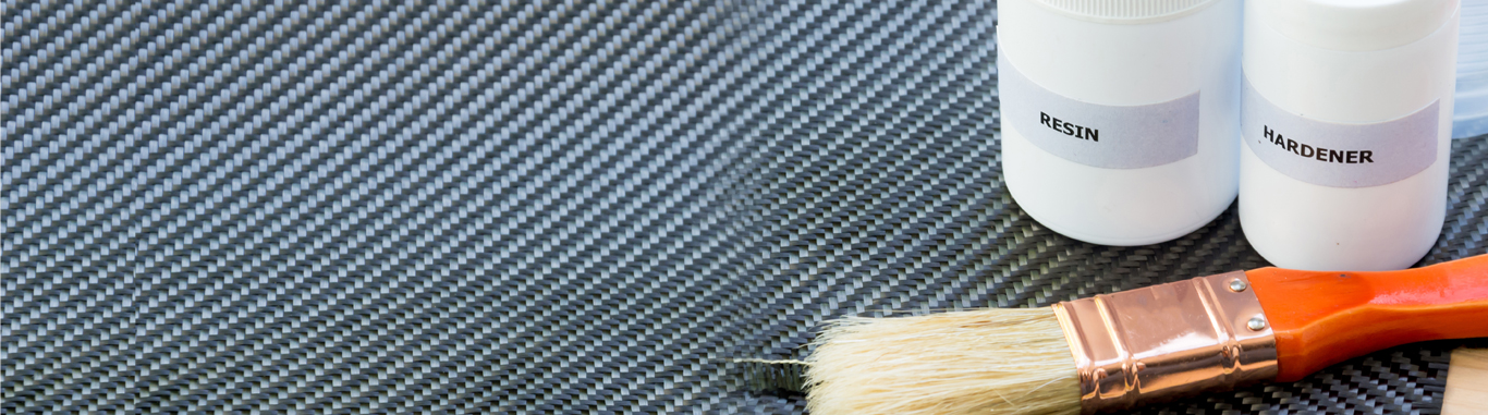
A. Open Molding – Open molding is the simplest and most widely used process to produce FRP parts. It is done in ambient shop conditions. The mold is generally fabricated from FRP. The cosmetic surface of the part is fabricated next to the mold. The back of the mold is open. While most fabrication processes involve the application of the exterior coating after the main structure of the part has been built, open mold parts are built from the exterior to the interior. The first step in open molding is to apply the gel coat (the exterior coating of the part) to the mold. The remaining layers of the laminate design, which will include some but not all of the following, back the gel coat :
1. Barrier Coat – this is applied behind the gel coat. A barrier coat improves part cosmetics, reduces cracking, and improves osmotic blister resistance in marine parts.
2. Skin Laminate – a relatively thin glass fiber reinforced laminate fabricated behind the gel coat. Skin laminates improve cosmetics and osmotic blister resistance.
3. Print Blocker – a sprayable syntactic foam material used behind a skin coat to improve laminate cosmetics.
4. Coring Materials – lightweight materials used to build part thickness and stiffness without adding weight.
5. Bulk Laminate – the main portion of the laminate that provides most of the structural properties.

Glass fiber reinforcement used in skin and bulk laminates can be applied by hand layup or spray-up techniques. Emissions from open mold processes are significant and are regulated by Federal NESHAP standards and, in some cases, State and Local regulations.

B. Low volume closed Molding –
The category of low-volume closed molding processes includes processes in which liquid resin is transferred into a closed cavity mold containing reinforcing materials. Over time, many variations of low-volume closed molding processes have evolved such as
• Vacuum infusion
• Seamann Composites Resin Infusion Manufacturing Process (SCRIMP®)
• Conventional RTM
• Light RTM (shell laminate RTM)
• Silicone bag RTM
• Closed Cavity Bag Molding (CCBM®)
• Multiple Insert Tooling (MIT®) RTM
• Zero Injection Pressure (ZIP®) RTM.

Parts fabricated using these processes may or may not have a gel coat on the exterior surface. The part size for these processes is limited by mold and part handling considerations. Part-to-part consistency is better than with open molding due to less dependence on operator skill. Also, two-sided cosmetic parts can be produced. Emissions from these processes are still regulated; however, they are much lower than with open molding due to the closed portion of the process. Emissions from the gel coat application, if used, are the same as for open molding.

C. Compression molding
Compression molding is another closed molding process. It uses clamping force during mold closure to flow a pre-manufactured compound through a mold cavity. A hydraulic press generally provides the clamping force. Compression molds are generally made from chrome-plated tool steel. Sheet molding compound, bulk molding compound, and wet molding compound are examples of pre-manufactured compounds.

If an external coating is needed on a compression molded part, it is generally post-applied; however, in-mold coatings are available. Part size is limited by press platen size. Part-to-part consistency is excellent. Emissions from compression molding are still regulated; however, they are much lower than with open molding due to the closed nature of the process.

The following table gives you the gist of the differences between the processes we just discussed

PROCESS COMPARISON
Part Characteristic
Open Molding
Low Volume
Closed Molding
Compression Molding
Maximum Part Size
Any Size
Any Size
Up to 100 Square Feet
Factors Limiting Part Size
Mold and Part Handling
Press Size
Part Surface
One Side
Two-Sided, Smooth or Textured
Part to Part Consistency
Fair
Good to Excellent
Excellent
Cross Section
Completely Variable
Better if Uniform
Easily Varied
Number of Parts Per Year
<1000
<10,000
>5,000
Parts Per 8-Hour Shift Per Mold
1-2
16-90
100-500
Mold Construction
Composite
Aluminum Nickel Shell, or
Composite
Chrome Plated Tool Steel
Mold Lead Time 2-4 Weeks 4-8 Weeks 16 Weeks or More
Tons of Composite Per Tons of Emissions 371 135-16302 135-16302

1. Numbers taken from unified emissions factors; 35 percent styrene content resin; mechanical non-atomized application; and 30 percent fiberglass.

2. Numbers are taken from EPA AP-42 emission factor; 35 percent styrene content resin; compound paste (25 to 100 percent resin); and 30 percent fiberglass.

Process Selection
When the best process to use for the fabrication of a specific part is not obvious, process selection should be accomplished through a process trade study. A process trade study involves comparing the part fabrication costs and part performance factors for a specific part fabricated by various processes. Part fabrication costs include but are not limited to equipment costs, tooling costs, material costs, and labor costs. Part performance factors are dependent on the specific part being studied but can include, weight, strength requirements, and appearance requirements. Emissions of Hazardous Air Pollutants (HAP) or other regulated materials vary by process and may also factor into process selection. An example trade study follows.

The subject part is from the deck of a run-about boat. It is a hinged hatch cover that provides access to an under-deck storage compartment or cooler. The step face features a non-skid profile on the external surface. The step face comprises glass skins over a foam-filled honeycomb core. The part measures 11 inches by 25 inches with a 1.5-inch tall perimeter flange. The design criteria include an impact of 300 pounds from a three-foot elevation.

The part is shown in Figure 1 alongside.
Processes considered in the trade study were open molding and several low-volume closed   


molding processes including vacuum infusion, silicone bag RTM, light RTM, and conventional RTM. Equipment costs, tooling costs, material costs, and labor costs were calculated for each process on a per-part basis.


Costs are based on typical values in the year 2005 and are presented as relative costs with open molding at 100 parts produced as the baseline. The number of parts to be produced varied from 10 to 9,000. Parts were to be produced over a three-year time frame with an equal number of parts per year. Process trade study cost results are shown in Table 1 below. The cost per part decreases as the number of parts produced increases. However, the amount of decrease depends on the process, meaning that Figure 1 Trade Study Hatch Cover different processes are the most cost-effective at different production rates.

Table 1- Process Trade Study Cost Results

Property Open Molding Vacuum Infusion Light RTM Silicone Bag RTM Conventional RTM
Part Appearance The part back side is rough The part back side is matte The part back side is smooth The part back side is matte The part back side is smooth
Strength Acceptable Comparable to open molding Comparable to open molding Comparable to open molding Comparable to open molding
Cost Effective Production Run Size <100 parts <200 parts 100 to 9,000 parts 100 to 9,000 parts >1000 parts
Emissions 0.126 lbs/part 0.064 lbs/part 0.064 lbs/part 0.064 lbs/part 0.064 lbs/part


Conventional RTM is not a cost-effective option for hatch cover production at production run sizes of less than 1000 parts. For production run sizes greater than 1,000 parts this process becomes competitive with light RTM, but does not become cheaper than light RTM even at production run sizes of 9,000 parts due to the need for a gel-coated surface.

The cost comparison could be different for large production runs of a non-gel
coated part. While competitive with light RTM, silicone bag RTM is never the cost-effective process for hatch cover production. This is due to the cost of the materials needed to fabricate the silicone bags. However, silicone bag RTM can be an excellent process selection for parts with closed contours that are not easily fabricated by other processes.

Light RTM is the low-cost process for hatch cover production at production run sizes greater than 100 parts.

Vacuum infusion is competitive with open molding as the low-cost process for hatch cover production runs of less than 100 parts. At higher production rates vacuum infusion is not cost-effective due to the cost of the consumable materials (vacuum bag film, sealant tape, etc.) needed for each part. Overall process trade study results including part appearance, strength, cost, and emissions, for the hatch cover, are shown in Table 2.

The use of closed a closed molding process reduces emissions by 50 percent in comparison to open molding with low VOC materials. The emissions differences as well differences in part appearance could influence process selection for hatch cover production.

This trade study is provided as an example of the type of evaluation that can be done to make an informed decision on process selection. The conclusions reached are not valid for all part types, sizes, complexity, and specific combinations of labor, material, and capital costs

Table 2. COMPARISON OF RTM PROCESSES
Property Open Molding Vacuum Infusion Light RTM Silicone Bag RTM Conventional RTM
Part Appearance Part back side is rough Part back side is matte Part back side is smooth Part back side is matte Part back side is smooth
Strength Acceptable Comparable to open molding Comparable to open molding Comparable to open molding Comparable to open molding
Cost Effective Production Run Size <100 parts <200 parts 100 to 9,000 parts 100 to 9,000 parts >1000 parts
Emissions 0.126 lbs/part 0.064 lbs/part 0.064 lbs/part 0.064 lbs/part 0.064 lbs/part

Open molding is the low-cost process for hatch cover production runs of less than 100 parts. But it is not cost-effective for production runs greater than 100 parts.

FRP Composites Graph

More information
This information on FRP composites is an extract from a book titled ‘Composites Application Guide’.

We hope you found this informative. Please feel free to share your articles in our future newsletters.


Info-Tutorial: Axel MoldWiz Sacrificial

Info-Tutorial:
Axel MoldWiz Sacrificial

Release: A 100% water-based Super Sacrificial Release
Semi-permanent mold releases (products that provide multiple release per application), are quite a trend, but sometimes a sacrificial mold release (applied every time a part is molded) may be a better choice.
For instance, it is perfect for winding/wrapping; compression molding, and some casting and laminating processes. Also, wherever a mold release is easily abraded during the molding process, the choice of a good sacrificial release is the best decision.
MoldWiz®WB-2700 is perfect in all the above cases. It provides good slip; is easy and quick to apply in the production cycle; is economical enough to be applied each time a part is molded; and does not cause build-up. The best part is that it is 100% water-based!
Filament Winding/Mandrel Wrapping

MoldWiz is suitable for large diameter polyester, vinyl ester and epoxy pipe production. The release can also be used for hand layup of flanges and pipe fittings. WB-2700 is also a good choice for wrapping applications that use epoxy prepreg. This includes the production of many recreational or sporting good items including: fishing poles; golf clubs;kayak and canoe paddles; mast and spars for sail boats and wind boards and more.
However, always check the condition and construction of mandrels before you use WB-2700. Mandrels that are of poor quality or condition require use of a release film or application of a thick wax to facilitate de-molding.
For all other mandrels, MoldWiz® WB-2700 is the ideal choice.
 
Pipe fittings
 
Compression Molding
In both hot and cold press Compression molding WB-2700 is an excellent choice since it can be applied to hot or cold molds. Since the product is 100% water-based pleasant for workers to use; requiring no special storage or handling, and is safe to use near hot equipment.
Compression molding DCPD resin
Polymer Concrete
Polymer concrete is a process that requires good release for a highly filled and abrasive resin mixture. Major industrial applications for polymer concrete include below grade electrical trenches and storage vaults. In these operations and others, WB-2700 has proven that it is a great mold release, providing dependable release for large parts and reducing the build-up that
occurred when using solvent/wax-based slurries, oils and other water-based mold releases.
 
Polymer concrete electrical trenches
Contact us
Plot No: 3B+3, Unit No: 6, D-1 Block, MIDC, Chinchwad, Opp. ADOR Welding Ltd, Chinchwad, Pune – 411019
Telefax: 020 – 30724590                            020 – 30727824
www.elink.co.in

Tech Focus: Fire Retardation in Polyester Resin: Part 2

Tech Focus: Fire Retardation in Polyester Resin: Part 2
R.Raghavan of Satyen Polymers educates us on Fire Retardation (FR) on Polyester Resins. This is a continuation of the section on Mechanism of flame Retardation.This is the last of a 2-part series.
Endothermic Decomposition
Decomposition occurs once the high binding energies between the individual atoms in the polymer are overcome. In general, decomposition occurs via free radical chain reactions initiated by oxygen or oxidizing impurities which are trapped in all plastics during manufacture. These free radicals are responsible for the flame spread in the combustion process.
When Ignition takes place!
The flammable gases that are formed by the decomposition process are mixed with atmospheric oxygen and ignited by an external flame, or alternatively by self-ignition if the temperature is sufficiently high compared to the oxygen to flammable gases ratio. When ignition occurs there is a thermal feedback due to the exothermic nature of the combustion process.
Flame spread
Thermal feedback from the combustion process provides more energy to the decomposition process during which new flammable gases are produced, thus feeding the combustion process. During flame spread the temperature of the polymer is typically 5000C-6000C while the temperature of the flame where the reaction with oxygen takes place is approximately 12000C.
How Smoke develops?
Smoke is a result of incomplete combustion and is a dispersion of solid/liquid particles in a carrier gas consisting of combustion gases and air. The liquid particles are tar-like droplets or mist composed of liquid product from pyrolysis; their partially oxidized derivatives, and water. The solid particles contain soot, ash, sublimed pyrolysis product and oxides of inorganic compounds.
Combustion product
The composition of gases during combustion of solid plastics is mainly dependent on the combustion temperature as well as the availability of oxygen.
The supply of oxygen and the temperature will vary constantly during the fire As a result the composition of the combustion gases will also vary. It is too complex to measure the composition of the gases through out the fire’s duration.
During combustion of a halogenated fire retardant polyester laminate, formation of gaseous Hydrogen Chloride, oxy chloride and/or Hydrogen Bromide, oxy Bromide will result in addition to the above mentioned combustion products.
When the fire occurs, what happens once a fire starts and how product design can render a product more resistant to ignition.

In addition to behaving as a fire retardant, it is very effective as a smoke suppressant in a wide range of polymers, most especially in polyesters, acrylics, ethylene vinyl acetate, epoxies, PVC, rubber.

An intumescent layer is a physical hindrance between the solid phase and the gaseous phase. This layer is formed by the combustion process and consists of inert gases and/or a solid crust that cools the solid phase by reducing heat transfer as well as shielding it from oxygen, breaking one side of the fire triangle. An intumescent layer may be formed by the introduction of phosphorous additives into the product.

Combination of these modes of action by use of different base resins and additives often results in a greater benefit (synergy) than if they were used individually. A common synergist with halogenated products is Antimony Trioxide (ATO).

Consequently it is possible to design composites with different degrees of smoke and flame spread performance to meet the various standards required by the end user.

Laminate Construction and Resin Usage
When designing and producing a laminate using a fire retardant resin, one should select a resin based on the required fire test criteria and end application.
Once this is done the following points which influence the performance of the end product should be taken into consideration – Content of glass, air voids, geometry and surface smoothness/thickness of laminate
Post curing
It’s important to maximize the glass content in finished laminates requiring fire retardancy not only because it acts as reinforcement,
but also due to its inertness to fire.
In general, one should aim to reduce air voids and ensure a smooth surface since these factors prevent the propagation of flames. By limiting the laminate thickness one ensures that the total amount of combustible material is low. On the other hand, a thin laminate heats up to the temperature at which decomposition occurs much sooner than a thick laminate.
Due to the low thermal conductivity of GRP laminates it takes a longer time to reach the decomposition temperature in a laminate of 4-8 mm, thus delaying both time to ignition and the propagation of fire.
The process of post curing reduces the amount of residual styrene in a laminate.
This concludes the 2 part series on FR Resins. We have a useful table on Fire tests and Classification sent in by Mr. R. Raghavan Please email us if you wish to have a copy.
Financial Year-end and
New year wishes
We are approaching the end of the current financial year, and we hope you will close on a high note! We wish you a successful Financial Year 2012-2013.
Contact us
Plot No: 3B+3, Unit No: 6, D-1 Block, MIDC, Chinchwad, Opp. ADOR Welding Ltd, Chinchwad, Pune – 411019
Tel. No. : 9657716495,                 9657716842,
Telefax: 020 – 30724590                            020 – 30727824
www.elink.co.in

Tech Focus: Fire Retardation in Polyester Resin: A Review

Tech Focus: Fire Retardation in Polyester Resin: A Review

R.Raghavan of Satyen Polymers Educates us on Fire Retardation (FR) on Polyester Resins. This is Part 1 of a 2-part series.

FR Resins – how important are technology and quality standards?
The major application areas of FR Resins are in Automobile, Transportation, Railways, Buildings and Structures, marine and roofing. The fire retardant composite is formulated to meet the IS, ASTM, DIN, BS & UL standards. The main focus in transportation / building applications are robust systems with low smoke and toxic emissions. This aids longer evacuation time. An FR formulation based composite should be adequately tested and certified by independent Agencies like ARAI, SGS, CIPET laboratories etc. for compliance. In the SPPL laboratory for instance, IS 6746 -1994 testing is done for each batch before dispatch. Fire retardant Fiberglass composite products are graded based on their halogenated /non-halogenated compounds.

Let’s go over the FR (fire retardation) process.

Fire and why it occurs?
Fire is a complex subject and occurs invariably due to unfortunate circumstances. No two fires are exactly the same. The materials involved are different; the essential oxygen supply to support the fire is different. Even the positioning of the flammable materials with respect to each other can have a drastic effect in the rate of progress of a fire and its intensity.

The resulting chemical reaction (fire) can be influenced (retarded) by any one of many components. It is necessary to assess the following factors in a real life fire:-

• Reduction of oxygen and increase     Development of high temperature
• Smoke/Direct consumption by fire
• Presence of toxic gases other than    carbon monoxide

Some of the properties to be examined:
• ease of ignition (ignitability)
• Spread of flame
• Heat evolution (release)
• Smoke
• Toxic gases

Important factors to be considered when discussing fire retardants with the end user.
1. End application of the composite     part and Processing
2. Halogenated or non-halogenated     and Requirements–Plain or filled
3. The Fire standard required and     classification of that standard
4. Laminate construction and design     thickness requirement
5. FR Gelcoat required –Y/N

Mechanism of flame Retardation Endothermic degradation:
Some compounds break down endothermically when subjected to high temperatures
Aluminum hydrates:
The reaction removes heat from the substrate, thereby cooling the material.
Thermal shielding:
A way to stop spreading of the flame over the material is to create a thermal insulation barrier between the burning and unburned parts.
Intumescent additives are often employed; their role is to turn the polymer into a char, which separates the flame from the material and slows the heat transfer to the unburned fuel.
Dilution of gas phase:
Inert gases (most often carbon dioxide and water) produced by thermal degradation of some materials act as diluents of the combustible gases, lowering their partial pressures and the partial pressure of oxygen, and slowing the reaction rate.
Gas phase radical quenching
• Chlorinated and brominated materials undergo thermal degradation and release hydrogen chloride and hydrogen bromide or if used in the presence of a synergist like antimony trioxide into antimony halides.
• These react with the highly reactive H· and OH. radicals in the flame, resulting in an inactive molecule and a Cl· or Br· radical.
• The halogen radical has much lower energy than H· or OH·, and therefore has much lower potential to propagate the radical oxidation reactions of combustion.
Fire retardant
Aluminium hydroxide also finds use as fire retardant filler for polymer applications at about 180 °C, absorbing a considerable amount of heat in the process and giving off water vapour.
Heating
• The GRP laminate is heated by an external heat source and in addition by thermal feedback once combustion has started.
• When heating provides sufficient energy, endothermic decomposition occurs
Part 2 on FR Resins will be published in the next Newsletter. 3 ARAI Reports in the context of this article have been uploaded on our website. Please have a look.
Contact us
Plot No: 3B+3, Unit No: 6, D-1 Block, MIDC, Chinchwad, Opp. ADOR Welding Ltd, Chinchwad, Pune – 411019
Tel. No. : 9657716495,                 9657716842,
Telefax: 020 – 30724590                            020 – 30727824
www.elink.co.in

Tech Focus: Sandwich Flow Mat – Importance & Benefits

Tech Focus: Sandwich
Flow Mat –
Importance & Benefits

The next level of development for a hand lay-up unit is to migrate to a mechanized molding format. The most popular such method is the closed molding process, with proven options like L-RTM. To enable this migration of technology, molders have to make changes at various stages of product development. This requires several changes in design of the component, lay-up sequence, raw materials and the finishing process.
Here we will focus on a different kind of glass reinforcement designed exclusively for the closed mold process. We are looking at a revolutionary product which imparts great design flexibility if you are using L-RTM or Resin Infusion process and Vacuum bagging etc., to manufacture your components. Let us look more closely at its importance and benefits.
Efficient resin flow:
One of the trickiest stages of the closed mold process is to design the resin flow and ensure it works. When the reinforcement is laid in place, the resin flow is obstructed by closely-held glass fibers made up of stitched mat or fabric. The flowing resin tends to carry with it glass strands creating ‘wet’ (resin rich) or ‘dry’ (resin deficient) spots. This creates a completely different product which will fail when unmolded, because of the improper strength distribution. It could also be damaged beyond repair. When you use a Sandwich Flow Mat, this hassle can be avoided.
Fast wet-out:
Economies of scale call for a fast process. So the resin has to spread through the component and
enable fast wet-out-to-cure time. Flow mat has a sandwich construction with three layers. The central core layer made of polymeric non-woven fibers works as the resin flow conduit. The glass reinforcement sits on either side of this to impart strength. Various GSMs of glass and central core are available to enable design flexibility and decide the glass loading required. The correct design allows producing components with higher glass content and optimized strength distribution within the component.
 

Sandwich Mat
Simplified tooling:
Due to easy resin flow along the length and breadth of the component, mold design using the Sandwich Flow Mat becomes very simple. This helps reduce the numbers of ‘in’ & ‘out’ ports for resin on the mold. The result is an overall less complicated set-up requiring reduced maintenance effort.
Optimized design:
The component lay-up sequence can be very easy and the flow mat works well with other forms of reinforcements like surface tissue, woven or non-woven fabrics or metal inserts in the component. Fabrics can sit over the flow mat and use the central core to supply resin along the component. With less demanding components, the flow mat alone satisfies the glass requirements. This completely does away with the need for other forms of reinforcements.
Improved surface finish:
Good resin flow and wet-out imparts a uniform surface finish along the entire component. The finer textures, contours and bodies on the component are molded with ease and accuracy giving the ‘perfect’ finish desired. This gives a dramatic reduction in finishing process time!
To summarize, these are the advantages of using the Sandwich Flow Mat:
• Optimised resin flow in thick parts. Suitable for polyester & epoxy resins.
• Time saving due to improved resin flow & fast wet-out
• High component quality due to controlled glass content
• Excellent & consistent surface finish
• Available in various options of GSM & core thickness
Link Composites is practically the sole distributor of this product in India, and stocks the entire range. Please contact us for a product demo or enquiry.

Last Word

Warm wishes on India’s 65th Republic Day!

We need your support to make this newsletter vibrant and interactive. Do send us your articles and case studies so that we learn and grow together!

Contact us
Plot No: 3B+3, Unit No: 6, D-1 Block, MIDC, Chinchwad, Opp. ADOR Welding Ltd, Chinchwad, Pune – 411019
Tel. No. : 9657716495,                 9657716842,
Telefax: 020 – 30724590                            020 – 30727824
www.elink.co.in

Influence of Carbon Nanotubes (CNTs) on Glass Fibre Reinforced Unsaturated Polyester Composites

by D. Selwyn Jebadurai and A. Suresh Babu

Glass fibre reinforced polyester composites have been utilized in many applications including automotive, transportation, structural, piping, chemical storage tanks and windmill components. Unsaturated polyesters are commonly used as matrix for GFRP composite parts as they have the advantages of low viscosity, fast cure time and low cost. Glass fibre is the most widely used reinforcement because of its features like high strength, corrosion resistance, easy availability and low cost.

In general, fibre reinforced polymers are known to have high in-plane tensile strength and stiffness properties and are much weaker in through thickness properties, such as the resistance to inter-laminar fibre-matrix cracking and delamination. The inter-laminar region is devoid of fibre reinforcement and fails via various modes, primarily delamination and matrix cracking which may develop through the service life of the structure. In recent years micro and nano-scaled particles have been considered as filler material for matrix resin to produce high performance composites with enhanced mechanical properties. Carbon Nanotubes (CNTs) have been the focus of research since their discovery by Sumio Iijima in 1991. CNTs have a combination of outstanding mechanical, electrical and thermal properties that make them suitable for numerous applications. The unique mechanical properties of CNTs as well as their low density and high aspect ratio make them ideal candidates to act as reinforcement for polymer composites. Functionalized MWCNTs lead to a more homogeneous distribution in the matrix and a reduced risk of agglomerates when compared to non-functionalized MWCNTs.

A study was conducted to analyse the influence of Carboxyl functionalized Multi-Walled Carbon Nanotubes (COOH – MWCNTs) on glass fibre reinforced polyester composites. CNTs were obtained from Quantum Materials Corporation, Bangalore. The average outer and inner diameters of nanotubes were 12 nm and 8 nm respectively.

The length of nanotubes were between 4 and 5 microns and their specific surface area were between 250 m2/g and 290 m2/g. Tensile strength of CNTs was found to be > 55 GPa. The Scanning Electron Microscope (SEM) and Transmission Electron Microscope (TEM) images of MWCNTs are shown in Figures 1 and 2 respectively.


Figure 1 SEM image of MWCNTs


Figure 2 TEM image of MWCNTs

Glass fibre reinforced unsaturated isophthalic polyester laminates were made without MWCNTs and with varying MWCNTs content (containing 0.2 and 0.5 wt% MWCNTs) by Vacuum Resin Infusion process. The composite laminates consisted of five layers of glass fibre mats. These five layers comprised of alternate layers of chopped strand mat (450 gsm) and woven roving mat (600 gsm). The MWCNTs were dispersed in the resin by ultrasonication for 1 hour and then the resin infusion process was carried out as shown in Figure 3. Specimens were characterized to determine tensile strength, tensile modulus, flexural strength, flexural modulus and inter-laminar shear strength (ILSS). The test results are shown in figures 4-8.

 Figure 3 Fabrication of Composite


  Figure 4 Comparison of Tensile Strength


Strength of Laminates

Composite laminate with 0.2 wt% MWCNT exhibited better mechanical properties than composite with 0.5 wt% MWCNT. It could be due to the homogenous dispersion of CNTs in the matrix at lower concentration. These homogeneously dispersed CNTs in the matrix act as interfaces for stress transfer and hence serve as additional nano-reinforcement to the matrix. Laminate with 0.2 wt% exhibited 58% increase in tensile strength and 235% increase in tensile modulus. There was a 23% increase in flexural strength and 13% increase in flexural modulus of the laminates with 0.2 wt% MWCNTs compared to laminates without MWCNTs. The inter-laminar shear strength was found to increase by 12% with 0.2 wt% MWCNTs. This study also shows that higher concentration of CNTs (0.5 wt%) leads to drop in mechanical properties which could be due to agglomeration of CNTs.
Further improvements in laminate properties can be achieved by optimizing the carbon nanotube content in the matrix. Thus there is huge potential to use carbon nanotubes in conventional fibre reinforced polymer composites for many structural applications. The safety aspects of handling virgin CNTs need to be understood clearly, although it is safe once they are incorporated in the matrix.


Figure 5 Comparison of Tensile Modulus
of Laminates


       Figure 6 Comparison of Flexural Strength
of Laminates


Figure 7 Comparison of Flexural Modulus
of Laminates


Figure 8 Comparison of Flexural Modulus
of Laminates
                                                                                                       

Info-Tutorial: Carbon

We at Link Composites were enthused by your response to our first newsletter. We are encouraged by your support, and look forward to being in regular touch with you from now on. If you would like us to cover a particular topic or vendor, please write in. We value your suggestions, and look forward to a better interaction with you through these newsletters.

Info-Tutorial: Carbon

Fibers (Contd. from previous issue): Key Markets, End Products

Key Markets and End Products

Wind Energy
India is now home to over 12 international and domestic wind turbine manufacturers including the likes of Suzlon, Vestas, WinWind, RRB Energy, etc. Plans are ongoing to manufacture blades with rotor diameters of 100M+ in India. Carbon fibers are the enabling material for blades above 45M in length. Zoltek has partnered with GBT (Global Blade Technology) from Netherlands to provide the wind energy industry with all the support tools its needs to move towards Carbon fibers.
CNG pressure Vessels
With the introduction of high tech buses in India that run on CNG there is a growing need to effectively manage the weight of the CNG cylinders that these buses are carrying. Type 2 (Metal Liner + Hoop wrap composite) and Type 3(Aluminum liner + Full wrap composite) have tremendous potential here. Currently all such cylinders continue to be imported and it’s only a matter of time before we see the commercial production of these cylinders domestically.
Infrastructure
Most of the bridges, building, piers etc., in India are now beginning to age. The Fiber wrapping of beams and columns for seismic retrofitting and structural rehabilitation represents an easy and cost effective solution to this problem. CFRP plates and Uni Directional Carbon fiber wraps are today widely being used to enhance the life of bridges and decks and to retrofit beams and columns.

Automotive

Europe and the Americas have now begun to look at carbon as a strategic material and there is a lot of activity surrounding the Carbon fiber/weight reduction and fuel efficiency programs of many automotive majors. There is a great potential for fabrics weavers, preform manufacturers, intermediate product form developers (SMC, BMC, LFT) and Tier 1 Automotive suppliers in India to be a part of this growth.
Oil & Gas
The Oil & Gas industry has a huge need for tethers, drill risers etc that need to be strong, stiff and corrosion resistant. Pultruded Carbon fibers work well in these environments. Buoyancy modulus utilizing milled carbon fibers are also in demand.
Electricity Transmission Cables
The High throughput HT transmission cable utilizes a carbon core conductor. The negative CTE (Coefficient of Thermal expansion) of Carbon offers the ability to build longer spans of cable.
Other products such as Aircraft secondary structures, Boat hulls, Propeller Shafts, Roller Blades, PC casings, X – ray tables, Orthotools, Carbon – Carbon brakes for Aircrafts and cars and sporting equipment offer tremendous scope for Composite fabricators to develop end products in Carbon with a minimal capital investment.
To summarize – The future of carbon fiber usage will be driven by the world’s need to Generate new forms of energy or reduce fossil fuel consumption to ensure a cleaner and greener tomorrow.
– Akhil Hebbar, Zoltek
We thank Mr. Hebbar for sharing this enlightening article with us.
In our Next Issue:
In our next newsletter our Info-Tutorial will focus on MoldWiz sacraficial release and its uses. Do send in your case-studies and articles for publishing in our YouSpeak column. Write to us at
response@elink.co.in
Contact us
Plot No: 3B+3, Unit No: 6, D-1 Block, MIDC, Chinchwad, Opp. ADOR Welding Ltd, Chinchwad,
Pune – 411019
Telefax: 020 – 30724590                            020 – 30727824
www.elink.co.in